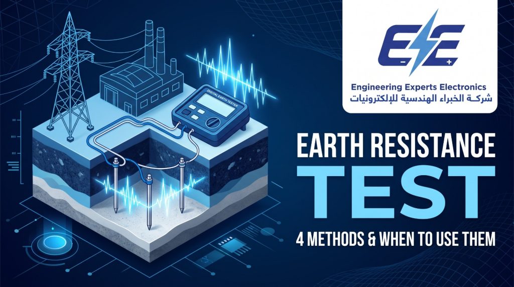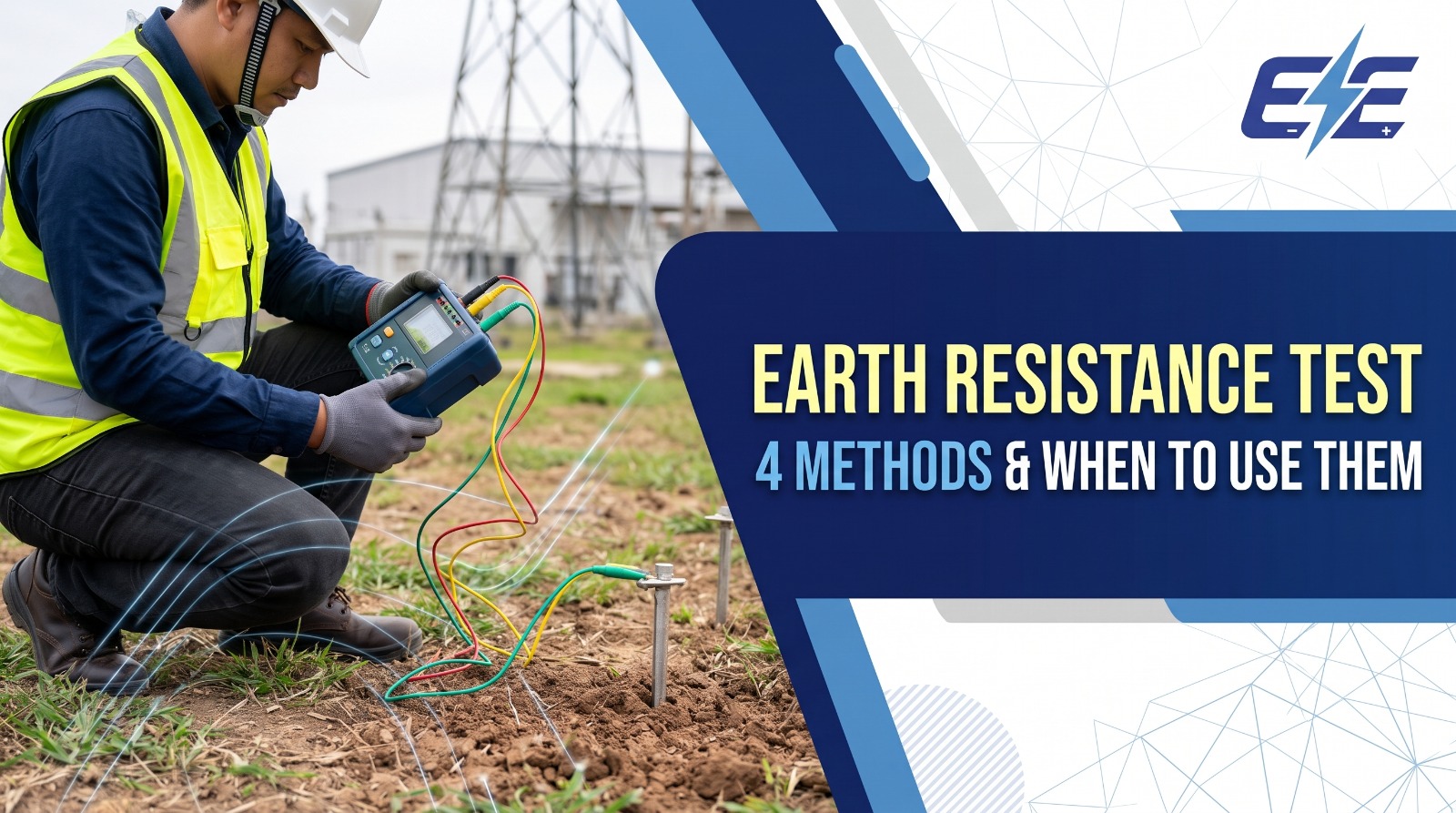
The four earth resistance testing methods, when to use each, the 62% rule, soil resistivity, acceptable values and how to choose an earth tester for Jordan’s dry, rocky ground. From EE Electronics, Amman.
In this article
Key takeaways
- An earth resistance test measures how well an earth electrode or earthing system conducts fault and lightning current into the ground.
- There are four main methods: fall of potential (3-pole), soil resistivity (4-pole Wenner), selective (stakes plus a clamp) and stakeless (clamp-on). Each suits a different job.
- There is no single “correct” value. Common targets range from 25 Ω for a single rod (NEC) to 5 Ω or less for industrial and telecom sites and 1 Ω or less for substations. The project specification always decides.
- Jordan’s dry, rocky ground makes low values harder to reach, and resistance is usually highest at the end of the dry summer. Test then, or record the conditions.
The earth resistance test is one of the most important checks on any electrical installation, and one of the most often done badly. An earthing system that looks perfect on the drawing can measure many times higher than its design value in dry, rocky ground, and a test done with the stakes in the wrong place can make a poor earth look good. The result is an installation that may not clear a fault quickly, may expose people to dangerous touch voltages, or may not protect against lightning.
This article from EE Electronics, a supplier of test and measurement equipment in Jordan for more than 30 years, explains the four earth resistance testing methods, when to use each, how to carry out the test correctly, what values to aim for, and how to choose an earth resistance tester for work in Jordan.
What is an earth resistance test?
An earth resistance test measures the resistance between an earth electrode, or a complete earthing system, and the general mass of the earth. That resistance decides how much current can flow into the ground during an earth fault or a lightning strike, and how high the voltage on the earthed metalwork rises while it does.
The resistance of an earth electrode has three parts: the resistance of the electrode and its connections (very small), the contact resistance between the electrode and the soil, and the resistance of the soil around it. The soil part dominates, which is why the same electrode can measure 20 Ω in one place and 300 Ω in another.
Why an earth resistance test is needed
- Safety: a low-resistance earth limits the voltage on exposed metalwork during a fault and helps protective devices disconnect quickly.
- Lightning and surge protection: lightning protection systems and surge protective devices need a good earth to dissipate energy safely.
- Equipment performance: telecom, IT and control systems need a stable reference and low noise.
- Compliance: utilities, consultants and insurers in Jordan ask for earth resistance test results at handover and during maintenance.
What affects earth resistance
| Type of earth | Average resistivity |
|---|---|
| Wet organic soil | 10 Ω·m |
| Moist soil | 100 Ω·m |
| Dry soil | 1,000 Ω·m |
| Bedrock | 10,000 Ω·m |
Soil type, moisture, temperature and dissolved salts all change resistivity, often by a factor of ten or more. The electrode matters too, but less than most people expect. According to Fluke, doubling the length of a rod reduces its resistance by up to 40%, while doubling its diameter reduces it by only about 10%. Adding rods helps, as long as they are spaced at least as far apart as they are deep, so that their “spheres of influence” do not overlap.
Acceptable earth resistance values
There is no single acceptable earth resistance value for every installation. The figures below are the ones most often quoted in specifications, and they show how widely the target depends on the application.
| Application | Typical target | Reference |
|---|---|---|
| Single rod, pipe or plate electrode | 25 Ω or less, or add a supplementary electrode | NEC 250.53 |
| Commercial and industrial systems | 1 to 5 Ω | IEEE 142 (Green Book) |
| Sensitive electronics, telecom sites | 5 Ω or less (often lower) | Industry practice |
| Lightning protection earth termination | 10 Ω or less, measured at low frequency (recommended) | IEC 62305-3 |
| TT installations protected by an RCD | RA × IΔn ≤ 50 V; values above 200 Ω may not be stable | BS 7671 |
| Substations | Typically 1 Ω or less; design is based on safe touch and step voltages | IEEE 80 practice |
Utilities, consultants and project specifications in Jordan often set their own value, for example a maximum for a substation earth grid, a telecom tower or a solar plant. Always test against the value in the specification, and state the method, the weather and the soil conditions in the earth resistance test report.
Two examples show how much the soil decides the result of an earth resistance test. Using the standard formula for a single vertical rod, a 3 m rod of 16 mm diameter in moist soil (100 Ω·m) gives roughly 30 Ω. The same rod in dry soil (1,000 Ω·m) gives roughly 300 Ω. In much of Jordan, a single rod will not meet a 5 Ω or even a 25 Ω target, and the design needs several rods, deeper electrodes or a mesh.
Earth resistance testing methods at a glance
Each method answers a different question. Choose by what you need to know and whether you can disconnect the electrode.
| Method | Measures | Needs | Disconnect? | Best for |
|---|---|---|---|---|
| Fall of potential | One electrode or system | 2 stakes | Yes | New installations, handover |
| Soil resistivity | The soil itself | 4 stakes | — | Designing an earthing system |
| Selective | One electrode in a system | 2 stakes + clamp | No | Sites with several electrodes |
| Stakeless | Loop in a multi-earthed system | Clamps only | No | Poles, telecom, routine checks |
Method 1: Fall of potential (3-pole) earth resistance test
The fall of potential method is the classic earth resistance test and the reference method in IEEE 81. The tester passes a known current between the electrode under test (E) and a current stake (H or C2) driven some distance away, and measures the voltage between the electrode and a potential stake (S or P2) placed between them. Resistance is voltage divided by current.
The electrode under test must be disconnected from the installation, so that the test current flows only through the electrode and not through other earth paths.
Where to place the stakes
Both stakes must be outside the electrode’s sphere of influence, in a straight line away from it. Fluke gives these typical distances for a single rod:
| Electrode depth | Potential stake | Current stake |
|---|---|---|
| 2 m | 15 m | 25 m |
| 3 m | 20 m | 30 m |
| 6 m | 25 m | 40 m |
| 10 m | 30 m | 50 m |
For a large earth grid, such as a substation, the current stake must be much further away. A common rule is at least five times the largest diagonal of the grid, which can mean hundreds of metres.
The 62% rule
IEEE 81 shows that, in uniform soil and with the stakes far enough apart, the true resistance is measured when the potential stake is at 61.8% (usually rounded to 62%) of the distance between the electrode and the current stake. With the current stake at 30 m, the potential stake goes at about 18.6 m.
The rule assumes uniform soil and that all the test current returns through the current stake. Neither is guaranteed on a real site, so always check the result.
How to check the result
- Move the potential stake. Repeat the measurement with the potential stake moved about 1 m towards and away from the electrode, or at 52% and 72% of the distance. If the readings agree closely, you are on the “plateau” and the result is valid.
- If the readings change a lot, the stakes are too close and their spheres of influence overlap. Fluke treats a change of about 30% as a sign the stakes are too close. Move the current stake further away and repeat.
- Use the right test frequency. Earth testers use frequencies away from 50 Hz to reject stray currents in the ground, which are common near substations and industrial plants.
- Make the site safeAgree the earth resistance test with the site owner. Disconnecting an earth electrode from a live installation removes protection, so isolate the supply or use the selective method instead.
- Disconnect the electrodeOpen the test link or disconnect the earthing conductor from the electrode under test.
- Drive the stakesDrive the current stake and the potential stake in a straight line away from the electrode, at the distances in the table.
- Connect and measureConnect E to the electrode, S to the potential stake and H to the current stake. Check the tester for noise or high stake resistance warnings, then take the reading.
- Check the plateauMove the potential stake and measure again. Record all readings, the distances, the weather and the soil condition.
- ReconnectReconnect the electrode and check the connection before restoring the supply.
Need an earth resistance tester for site work?
EE Electronics supplies 3-pole, 4-pole and clamp-on earth resistance testers with stakes, cable reels and calibration certificates. Tell us how you test and get a quotation within 24 hours.
Method 2: Soil resistivity test (4-pole Wenner method)
Before an earthing system is designed, the engineer needs to know the resistivity of the soil. The Wenner method, defined by Frank Wenner of the US Geological Survey in 1915, uses four stakes driven in a straight line at equal spacing a. The tester injects current through the outer two stakes and measures the voltage between the inner two.
Here ρ is the soil resistivity in Ω·m, a is the stake spacing in metres and R is the reading in ohms. The simple formula holds when the stakes are driven no deeper than about one tenth of the spacing. For example, with a spacing of 3 m and a reading of 5.3 Ω, the soil resistivity is 2π × 3 × 5.3 ≈ 100 Ω·m.
Because the measurement represents the soil down to a depth roughly equal to the spacing, engineers repeat it at several spacings (for example 1, 2, 4, 8 and 16 m) and in more than one direction. Plotting resistivity against spacing shows whether the soil changes with depth, for example a dry, high-resistivity surface layer over moister ground, which tells the designer whether deep rods will help.
Soil resistivity testing needs a 4-terminal earth tester. A 3-terminal tester can measure an electrode, but not soil resistivity.
Method 3: Selective earth resistance test
Disconnecting an electrode is not always possible or safe, especially on a live site. The selective earth resistance test solves this. It uses the same two stakes as the fall of potential method, plus a current clamp placed around the earthing conductor of the electrode under test. The tester measures only the part of the test current that flows through that electrode, so the result is the resistance of that electrode alone, even while it stays connected to the rest of the system.
Selective testing is ideal for buildings with several earth electrodes, lightning protection systems with multiple down-conductor earths, and substations or telecom sites where disconnecting the earth would be unsafe or disruptive. Fluke notes that a stake spacing of about 20 m is usually sufficient.
Method 4: Stakeless (clamp-on) earth resistance test
The stakeless method uses no stakes at all. A clamp-on earth tester, or two clamps connected to an earth tester, induces a voltage in the earthing conductor and measures the current that flows. The result is the resistance of the loop: the electrode under test plus all the other earth paths in parallel.
When there are many parallel paths, such as a line of utility poles each with its own earth, the parallel resistance is very low and the reading is close to the resistance of the electrode under test. That makes the clamp-on earth resistance test very fast for routine checks on distribution networks and telecom sites.
| Situation | Result |
|---|---|
| Many parallel earths (poles, multi-earthed neutral) | Works well; quick and accurate |
| Single isolated rod | Does not work: there is no return path, the tester shows open circuit |
| Earth bonded to building steel or metal pipes | Can read falsely low: the current loops through metal, not the soil |
| Need for an absolute value at handover | Use fall of potential instead |
Seasonal variation: when to do an earth resistance test
Earth resistance changes with the seasons because soil resistivity depends on moisture and temperature. An IET article on TT earthing gives an example for a sandy loam: its resistivity rises from 72 Ω·m at 20 °C to 99 Ω·m at 10 °C, and much higher if the ground freezes. Drying has a similar effect, which is why BS 7671 requires electrodes to be installed so that soil drying and freezing will not raise their resistance above the required value.
In Jordan, rain falls mainly in winter and the summer is long and dry, so earth resistance is usually at its highest at the end of the summer. A test in February after heavy rain can look much better than the same earth in September.
- Test at the driest time of year when you can, or record the weather and soil condition with every result.
- Test new installations before handover, and after any change to the earthing system.
- Repeat periodically. In the lightning protection industry, testing every 11 months is widely used so that results move through the seasons.
- Trend results against earlier tests by the same method; a steady rise points to corrosion or loose connections.
What to do if the earth resistance test result is too high
- Drive deeper: longer rods reach moister soil; doubling the length can cut resistance by up to 40%.
- Add electrodes: more rods in parallel, spaced at least as far apart as they are deep.
- Use a mesh or foundation earth: a buried grid or foundation electrode spreads current over a large area.
- Improve the soil around the electrode: earth enhancement compounds lower contact resistance in rocky or dry ground.
- Check the connections: a corroded clamp or a loose link adds resistance; a multifunction installation tester or a low-resistance continuity test finds it.
Measure the soil resistivity first with the Wenner method. It shows whether deeper rods or a wider mesh will give the bigger improvement.
Earth resistance testing in Jordan
Jordan is a challenging place to build a low-resistance earth. Much of the country is dry, and a lot of construction sits on limestone hills or desert ground, where resistivity can be in the range IEEE 80 gives for dry soil and bedrock (1,000 to 10,000 Ω·m). Many of the country’s large solar plants are built in desert areas such as Ma’an and Mafraq, where long, dry summers push resistivity higher still.
That makes testing more important, not less. Typical earth resistance test work in Jordan includes:
- Substations on the NEPCO, JEPCO, IDECO and EDCO networks, from 132/33 kV grid stations to 11/0.4 kV distribution substations.
- Solar and wind plants, where the earthing of inverters, transformers and module structures is tested at commissioning.
- Telecom towers and data centres, which usually need low values and regular checks.
- Buildings, hospitals, factories and fuel stations, including lightning protection earths.
For solar plants, earth continuity and bonding are also part of the IEC 62446-1 commissioning tests, together with insulation resistance; see our article on choosing an insulation resistance tester. For a full view of what each type of team needs, see our electrical testing equipment list for Jordan.
Need earthing tests as a service?
Our partner AQ Electric carries out on-site testing and commissioning across Jordan and the region, including solar PV testing in Jordan to IEC 62446-1.
Choosing an earth resistance tester
Earth resistance testers range from simple 3-pole instruments to complete kits that support all four methods. Match the tester to the earth resistance test methods you need.
| Type | Methods | Typical user |
|---|---|---|
| 3-pole tester | Fall of potential | Electricians, building installations |
| 4-pole tester | Fall of potential and soil resistivity | Designers, solar and substation contractors |
| Full kit with clamps | All four methods | Testing companies, utilities, telecom |
| Clamp-on earth tester | Stakeless only | Quick routine checks on multi-earthed systems |
Whichever type you choose, check these points:
- The methods you need: 3-pole, 4-pole, selective and stakeless.
- Good noise rejection and a test frequency away from 50 Hz, for sites near substations.
- Warnings for high stake resistance and interference, so you know when a reading is not reliable.
- A kit with stakes and cable reels long enough for your largest sites (for example 25 m and 50 m).
- Data storage and reporting for handover documents.
- A calibration certificate and local support in Jordan.
Most leading brands offer earth testers. Fluke’s 1625-2 GEO supports all four methods, Megger’s DET4T range covers 3-pole and 4-pole testing, and Kyoritsu, Sonel, Metrel and Chauvin Arnoux offer both stake and clamp-on testers. If you are also choosing an insulation tester, our Fluke vs Megger insulation tester comparison may help.
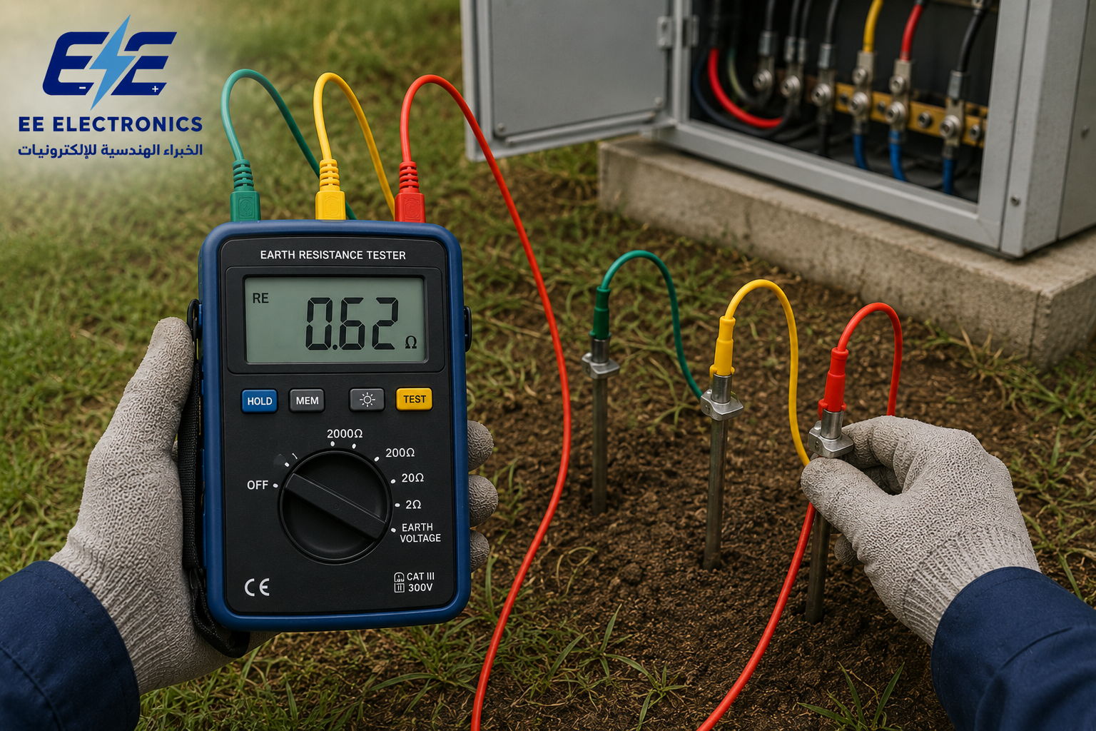
- 3-pole, 4-pole, selective and stakeless testing
- Complete kits with stakes, reels and clamps
- Calibration certificate and local support
Before you order, our article on buying test equipment in Jordan lists ten checks, from authorised supply to calibration certificates.
Not sure which earth tester you need?
Tell EE Electronics what you test: single rods, buildings, substations or telecom sites. We will recommend the right earth resistance tester and kit, and reply within 24 hours.
Earth resistance testers from EE Electronics
EE Electronics has supplied test and measurement equipment in Jordan for more than 30 years, from its office in Khalda, Amman. We supply earth resistance testers from leading brands, together with the rest of the electrical test equipment an electrical team needs. See all the brands we supply.
- The right method for the job: 3-pole, 4-pole, selective or clamp-on, matched to your sites.
- Complete kits: stakes, cable reels, clamps and carrying cases, so nothing is missing on site.
- One quotation for earth testers, insulation testers, clamp meters and installation testers.
- Calibration certificate with the instrument, and support from our Amman office.
- Training through our electrical testing and commissioning training.
Earth testing equipment in Jordan
Earth resistance testers and the instruments used alongside them, from EE Electronics in Amman.
3-pole, 4-pole, selective and clamp-on.

Electrical Installation Testers
Earth, loop, RCD and insulation in one.
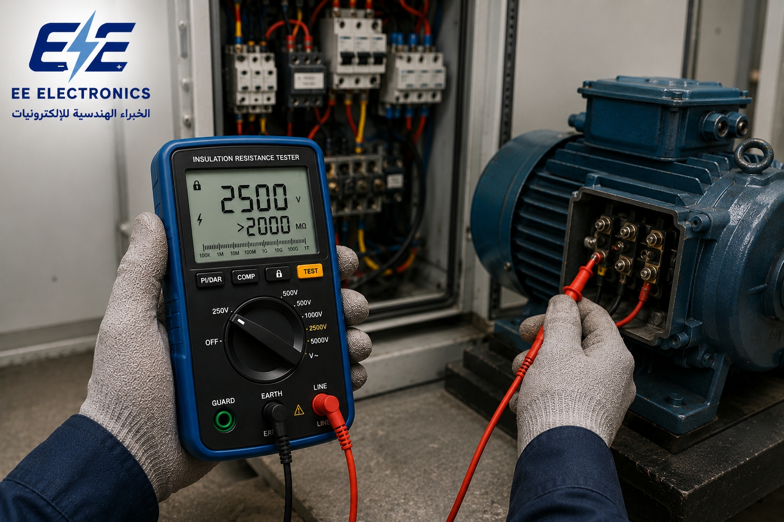
The test that goes with every earth test.

Leakage and earth conductor current.

Voltage checks before and after testing.

Hot earth connections and bonds.
Browse by category
 Electrical & Electronic EquipmentEarth, insulation, clamp and installation testers
 MV/HV Test EquipmentSubstation and transformer testing
 Solar PV Testing EquipmentPV testers, IV curve tracers
 Safety & Protection EquipmentHV detectors, gloves, earthing sets
 Measurement & CalibrationElectrical, process and temperature calibrators
 Training & Engineering SolutionsTesting, calibration and safety training
Frequently asked questions
What is an earth resistance test?
An earth resistance test measures the resistance between an earth electrode or earthing system and the general mass of the earth. It shows whether the earth can carry fault and lightning current safely into the ground.
What is an acceptable earth resistance value?
It depends on the application and the specification. Common targets are 25 Ω or less for a single rod (NEC), 1 to 5 Ω for commercial and industrial systems (IEEE 142), 10 Ω or less for lightning protection (IEC 62305-3) and typically 1 Ω or less for substations.
What is the 62% rule in earth testing?
In the fall of potential method, IEEE 81 shows that the true resistance is measured when the potential stake is placed at about 62% of the distance between the electrode and the current stake, assuming uniform soil and stakes far enough apart.
How is soil resistivity measured?
With the 4-pole Wenner method: four stakes in a line at equal spacing a, current through the outer pair and voltage across the inner pair. Resistivity is ρ = 2πaR, and it represents the soil down to a depth of about a.
Can an earth resistance test be done without disconnecting the electrode?
Yes, with the selective method (two stakes plus a clamp) or the stakeless clamp-on method. The fall of potential method requires the electrode to be disconnected.
Why does earth resistance change with the seasons?
Soil resistivity depends on moisture and temperature. Dry or frozen soil has a much higher resistivity, so earth resistance in Jordan is usually highest at the end of the dry summer.
How often should an earth resistance test be done?
At handover, after any change, and then periodically. Many lightning protection specialists test every 11 months so that results move through the seasons; follow your specification or maintenance plan.
Where can I buy an earth resistance tester in Jordan?
EE Electronics supplies 3-pole, 4-pole and clamp-on earth resistance testers and complete kits from its office in Khalda, Amman, with calibration certificates and local support. Send your requirement for a quotation within 24 hours.
Testing earthing systems in Jordan? Get the right earth tester.
Tell EE Electronics what you test and which methods you need. We will recommend the right earth resistance tester and kit, and reply with a quotation within 24 hours.