How the TTR test works, the TTR test procedure step by step, expected ratios for three-phase vector groups, the ±0.5% acceptable limits and how to read the results. From EE Electronics, Amman.
In this article
Key takeaways
- A TTR test compares the measured turns ratio of each winding pair with the ratio calculated from the nameplate and vector group.
- The usual acceptance limit is ±0.5% of the calculated ratio (IEEE C57.12.00 and C57.152). IEC 60076-1 uses the lower of ±0.5% or one tenth of the percentage impedance.
- Test every tap, every phase, and record phase deviation and excitation current as well as the ratio. Shorted turns can hide behind a ratio that looks normal.
- Use a TTR tester at least five times more accurate than the limit you are checking: ±0.1% or better for a ±0.5% limit.
The TTR test is one of the first tests run on any power or distribution transformer, and one of the most useful. In a few minutes, a transformer turns ratio test shows whether every winding has the right number of turns, whether the tap changer selects the right taps, and whether the windings are connected in the vector group stated on the nameplate. It finds shorted turns, open windings and wrong connections before a transformer is energised, and it is the first test engineers reach for after a transformer trips.
This article from EE Electronics, a supplier of test and measurement equipment in Jordan for more than 30 years, explains how the TTR test of a transformer works, sets out the TTR test procedure step by step, shows how to calculate the expected ratio for three-phase vector groups, and explains the acceptable limits and how to read the results. It closes with what to look for in a TTR tester and how TTR testing fits into transformer commissioning and maintenance in Jordan.
What is a TTR test?
TTR stands for transformer turns ratio. A TTR test measures the ratio between the number of turns in the high-voltage (HV) winding and the number of turns in the low-voltage (LV) winding on the same core limb, and compares it with the ratio the transformer should have.
For an ideal transformer, the voltage ratio equals the turns ratio:
A TTR tester applies a low AC voltage to one winding, measures the voltage induced in the other, and calculates the ratio. Because the test voltage is low and the transformer is unloaded, the measurement is close to the true turns ratio. Modern instruments also measure the phase deviation between the two voltages and the excitation current drawn by the energised winding, which turn a simple ratio check into a diagnostic test of the windings and the core.
Turns ratio, voltage ratio and nameplate ratio
Three ratios are easy to confuse, and mixing them up is the most common cause of a “failed” TTR test on a healthy transformer.
| Ratio | What it means | Example |
|---|---|---|
| Nameplate ratio | Rated HV line voltage ÷ rated LV line voltage, as printed on the nameplate | 11,000 / 400 V = 27.50 |
| Voltage ratio | Ratio of the voltages measured across the two windings being compared | Depends on how the windings are connected |
| Turns ratio | Ratio of turns on one winding pair on the same core limb; what a TTR tester measures | 47.63 for an 11/0.4 kV Dyn11 unit |
For a single-phase transformer, all three are the same. For a three-phase transformer, the turns ratio per phase depends on the vector group, and the TTR tester has to be told (or detect) the vector group so it can compare like with like. The worked examples further down show how.
Why the TTR test matters
The turns ratio is fixed when the transformer is wound. If it changes, something inside the transformer has changed. A transformer turns ratio test detects:
- Shorted turns, where insulation between adjacent turns has failed. Shorted turns effectively remove turns from a winding and change the ratio, often by a small amount.
- Open windings and broken internal connections, which give no reading or a large error.
- Wrong connections and an incorrect vector group, typically after repairs or rewinding.
- Tap changer faults: wrong tap positions, worn or misaligned contacts, and incorrect tap leads.
- Damage from transport, through-faults or overloading, when the result is compared with factory or earlier test results.
Because the transformer turns ratio test is quick, safe and uses low voltage, it is run at every stage of a transformer’s life.
| Stage | When | What it confirms |
|---|---|---|
| Factory acceptance | Routine test on every transformer before dispatch | Factory baseline for later comparison |
| Site acceptance | After delivery and installation, before energising | Transport damage, wrong taps or connections |
| Routine maintenance | At the interval in the maintenance plan | Slow deterioration, tap changer wear |
| After a trip or fault | Before re-energising after a differential or Buchholz trip | Shorted turns, winding damage |
| After repair or relocation | After rewinding, tap changer work or moving the unit | Correct connections and vector group |
A TTR test is usually run together with winding resistance, insulation resistance, tan delta and, on larger units, SFRA tests. Together they give a complete picture of the windings, the core and the insulation.
How a TTR tester works
A TTR tester energises one winding with a stable AC voltage and measures the induced voltage on the other winding with high accuracy. Most instruments energise the HV winding and measure the LV winding (step-down mode); some can also energise the LV side (step-up mode).
Typical test voltages are low. Hand-held single-phase testers commonly use 8 V rms, and as little as 1.5 V for current transformers. Benchtop and three-phase testers offer higher voltages such as 40 V and 80 V, and true three-phase testers can apply up to around 250 V. A higher test voltage excites the core better, which improves accuracy on high-ratio transformers. Megger’s field research, for example, recommends a higher voltage such as 80 V for high-ratio units.
| Measurement | What it is | What it finds |
|---|---|---|
| Turns ratio | Ratio of each winding pair, compared with the calculated ratio | Shorted or open turns, wrong taps |
| Ratio error (%) | Deviation from the calculated ratio | Pass/fail against ±0.5% |
| Phase deviation | Angle between the HV and LV voltages, in minutes or degrees | Core problems, partial shorted turns |
| Excitation current | Current drawn by the energised winding, in mA | Shorted turns, core faults, unintended core grounds |
| Polarity / vector group | Relative polarity and phase displacement of the windings | Wrong connections |
Single-phase and three-phase TTR testers
A single-phase TTR tester measures one winding pair at a time. On a three-phase transformer, the user moves the leads (or a switch box changes the connections) for each phase. A three-phase TTR tester connects to all six or eight bushings at once, excites all three phases, switches the measurements internally, and reports the full transformer in seconds. Field results published by Megger show that three-phase excitation gives smaller and more consistent errors than single-phase excitation, especially on transformers with delta-connected windings and on-load tap changers.
Need a TTR tester for transformer commissioning?
EE Electronics supplies hand-held, single-phase and three-phase TTR testers for distribution and power transformers in Jordan. Tell us your transformer ratings and get a quotation within 24 hours.
TTR test procedure, step by step
The exact connections depend on the instrument, but every TTR test procedure follows the same sequence. Always follow the instrument manufacturer’s instructions and your site’s safety rules.
- Isolate, prove dead and earthObtain the permit to work, isolate and lock out the transformer on all sides, prove dead with a suitable voltage detector and apply earths. Wear the safety equipment your procedure requires.
- Disconnect external connectionsDisconnect the HV and LV cables or busbars from the bushings, or at least make sure nothing connected to the transformer can load or back-feed the windings. Clean the bushing terminals for a good contact.
- Record the nameplate dataWrite down the rated voltages for every tap, the vector group (for example Dyn11), the tap changer type and the number of tap positions. Note the tap position the transformer is set to.
- Connect the test leadsConnect the H leads to the HV bushings and the X leads to the LV bushings, matching polarity (H1 to the HV terminal that corresponds to X1). Connect the tester to earth as instructed.
- Enter the vector group and select the test voltageEnter the vector group and nameplate voltages so the tester calculates the expected ratio for each phase. Choose the test voltage; use a higher voltage for high-ratio transformers if the tester allows it.
- Measure every phase on every tapMeasure the ratio, phase deviation and excitation current on each phase. Repeat for every tap position of the off-circuit tap changer, and for every position of an on-load tap changer.
- Compare and recordCompare each result with the calculated ratio and with factory or earlier results, and save the report. Return the tap changer to its service position and remove the earths only when the permit allows.
A DC winding resistance test leaves residual magnetism in the core, which can distort excitation current readings. Run the TTR and excitation current tests first, or demagnetise the core after the DC tests. Many modern winding resistance testers include a demagnetising function.
If the excitation leads are connected to the LV winding and the tester is set to energise the HV side, the HV winding will see the test voltage multiplied by the ratio. On a high-ratio transformer this can produce dangerous voltages at the HV bushings. Check the connections before every test.
Calculating the expected ratio for three-phase transformers
On a three-phase transformer, the TTR tester measures one HV winding against the LV winding on the same core limb. Whether that winding sees the line voltage or the phase voltage depends on whether it is connected in delta or star, so the expected turns ratio is the nameplate ratio multiplied or divided by √3 (1.732).
| Vector group | Winding connection | Expected turns ratio |
|---|---|---|
| Dd0, Yy0, YNyn0 | Same type on both sides | Nameplate ratio |
| Dyn11, Dyn1, Dy11 | Delta HV, star LV | Nameplate ratio × √3 |
| YNd1, YNd11, Yd11 | Star HV, delta LV | Nameplate ratio ÷ √3 |
| Single-phase | One winding pair | Nameplate ratio |
Most modern TTR testers apply these factors automatically once the vector group is entered, but it is worth checking the calculation by hand on the first test of the day. Four examples:
Testing every tap position
Distribution transformers usually have an off-circuit tap changer with five positions, typically ±2 × 2.5% on the HV winding. Each tap changes the HV turns, so each tap has its own expected ratio and its own ±0.5% acceptance band. The table shows the figures for an 11/0.4 kV Dyn11 transformer.
| Tap | HV voltage | Expected turns ratio | ±0.5% band |
|---|---|---|---|
| Tap 1 | 11,550 V (+5%) | 50.01 | 49.76 – 50.26 |
| Tap 2 | 11,275 V (+2.5%) | 48.82 | 48.58 – 49.07 |
| Tap 3 (principal) | 11,000 V (0%) | 47.63 | 47.39 – 47.87 |
| Tap 4 | 10,725 V (-2.5%) | 46.44 | 46.21 – 46.67 |
| Tap 5 | 10,450 V (-5%) | 45.25 | 45.02 – 45.48 |
Testing every tap matters because a fault can sit on one tap only: a burnt contact, a broken tap lead or a selector out of position. If every tap reads correctly except one, the fault is almost certainly in the tap changer or its leads rather than the main winding.
For on-load tap changers (OLTCs), the ratio is measured on every OLTC position. Where a transformer has both an OLTC and an off-circuit tap changer, NETA’s recommended practice is to test each OLTC position against one off-circuit position, and each off-circuit position against one OLTC position.
TTR test acceptable limits
The TTR test acceptable limit for ratio is well established. The figures below are the ones most consultants and utilities refer to.
| Reference | Limit | Where it is used |
|---|---|---|
| IEEE C57.12.00 / C57.152 | Within ±0.5% of the nameplate (calculated) ratio, with rated voltage on one winding at no load | Most common limit in specifications |
| IEC 60076-1 | Principal tap: the lower of ±0.5% of the declared ratio or ±1/10 of the percentage impedance. Other taps: to be agreed, but not less than that value | Common in IEC-based projects |
| NETA ATS / MTS | Not more than 0.5% from the calculated ratio or from adjacent coils | Acceptance and maintenance testing |
Note the IEC rule. A distribution transformer with 4% impedance gets a tolerance of 0.4%, not 0.5%, on the principal tap. Check the impedance on the nameplate when you test to an IEC-based specification.
On transformers with on-load tap changers and a small number of LV turns, a single tap step can exceed 0.5%. In these cases Megger’s guidance, based on IEEE C57.152, is that the extreme taps should be within ±0.5% and all three phases should show the same ratio on every tap.
A worked example
An 11/0.4 kV Dyn11 transformer on the principal tap has an expected turns ratio of 47.63. The TTR tester measures 47.81 on phase A:
Passing is not the whole story. If phases B and C both read 47.64, phase A is the odd one out, and a difference of nearly 0.4% between phases deserves a closer look at the excitation current and winding resistance on that phase.
Limits for phase deviation and excitation current
There is no single pass/fail number for phase deviation or excitation current. Both are judged by comparison:
- Between phases. On a three-limb core-type transformer, excitation current normally follows a high-low-high pattern: the two outer phases draw similar, higher currents and the middle phase draws less. An outer phase that is clearly different from the other outer phase is a warning sign.
- Against earlier results. Compare with the factory test report, the commissioning results, or the same model of transformer. A rise in excitation current or phase deviation over time points to developing core or winding problems.
- Between taps. Readings should change smoothly from tap to tap. A jump on one tap points to the tap changer.
Megger published a case where a transformer that tripped on a turn-to-turn fault gave ratio results that looked very good. The excitation current told a different story: phase A drew 257 mA at a 100 V test voltage, strong evidence of the shorted turn. Always record excitation current alongside the ratio.
How to read TTR test results
When a TTR test result is outside the limits or inconsistent between phases, the pattern usually points to the cause. Use the table as a starting point, then confirm with other tests.
| What you see | Likely cause | Next step |
|---|---|---|
| Ratio low on one phase, high excitation current | Shorted turns in the HV winding of that phase | Winding resistance, SFRA, oil analysis |
| Ratio high on one phase, high excitation current | Shorted turns in the LV winding of that phase | Winding resistance, SFRA |
| No reading or very large error | Open winding, broken lead or loose connection | Winding resistance, visual inspection |
| Error on one tap only | Tap changer contact, lead or position fault | Winding resistance on every tap, tap changer inspection |
| All phases off by about 1.732 times | Wrong vector group entered, or wrong connections | Check nameplate and lead connections |
| Polarity or vector group mismatch | Wrong internal or external connections after repair | Re-check connections before energising |
| Large phase deviation | Core problems or partial shorted turns | Excitation current, SFRA |
| Excitation current high on all phases | Residual magnetism, core fault or unintended core ground | Demagnetise and retest, core insulation test |
If the TTR test raises a doubt, do not energise the transformer until the cause is understood. A shorted turn carries a very high circulating current when the transformer is energised and can develop into a major internal failure within minutes. Hot spots on connections and bushings in service can also be checked with a thermal imaging camera, but that does not replace offline tests such as the TTR test.
TTR test and other transformer tests
The TTR test answers one question: are the turns and connections correct? Transformer commissioning and condition assessment need several tests, each answering a different question.
| Test | What it finds | Instrument |
|---|---|---|
| Turns ratio (TTR) | Shorted or open turns, taps, vector group | TTR testers |
| Winding resistance | Loose connections, broken strands, tap changer contacts | Winding resistance testers |
| Insulation resistance and PI | Moisture and contamination in the insulation | 5–15 kV insulation testers |
| Tan delta / power factor | Ageing and moisture in the insulation and bushings | Tan delta testers |
| SFRA | Winding deformation and core movement after transport or faults | SFRA analyzers |
| Oil breakdown voltage | Moisture and particles in the insulating oil | Oil BDV testers |
| CT and VT ratio | Ratio, polarity and accuracy of instrument transformers | CT/PT analyzers |
The insulation resistance test deserves a special mention because it is usually run first. Our article on choosing an insulation resistance tester explains test voltages and PI limits for transformer windings. For the cables that connect the transformer, see our article on VLF cable testing. And if you are building a complete testing kit, our electrical testing equipment list for Jordan groups the instruments by job.
Choosing a TTR tester
TTR testers range from pocket-size single-phase instruments to automatic three-phase systems for substations. The right choice depends on the transformers you test and how often.
| Hand-held | Benchtop | Three-phase | |
|---|---|---|---|
| Best for | Distribution units, CTs and VTs | Regular power transformer testing | Substations, OLTCs, high volumes |
| Test voltage | 8 V (1.5 V for CTs) | e.g. 8, 40 and 80 V | Up to about 250 V |
| Connections | One phase at a time | Per phase or switch box | All bushings at once |
| Speed, 3-phase unit | Minutes per tap | Faster with switch box | Seconds per tap, auto OLTC |
| Reports | Basic memory | Memory, PC software | Test plans, PDF and Excel |
Whichever type you choose, check these points in the specification:
- Ratio range covers your highest-ratio transformer, and CTs and VTs if you test them.
- Accuracy of ±0.1% or better in the ratio range you use, five times better than the ±0.5% limit.
- Phase deviation and excitation current measured on every test, not just the ratio.
- Vector group entry or automatic detection, with √3 factors applied automatically.
- Test voltage high enough for your high-ratio transformers.
- Automatic tap sequences for transformers with on-load tap changers.
- Report software that produces the test sheets your consultant or utility asks for.
- A calibration certificate with the instrument, and local support and recalibration.
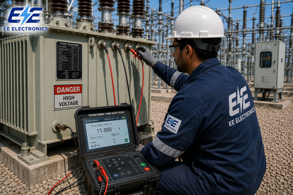
Transformer Turns Ratio (TTR) Testers
- Hand-held, single-phase and true three-phase TTR testers
- Ratio, phase deviation, excitation current and vector group
- Automatic tap sequences and test reports
Before you order, our article on buying test equipment in Jordan lists ten checks, from authorised supply to calibration certificates and delivery terms.
Not sure which TTR tester fits your transformers?
Send EE Electronics the ratings of your largest and smallest transformers and whether they have on-load tap changers. Our engineers will recommend the right TTR tester and reply within 24 hours.
TTR testing in Jordan
Jordan’s grid relies on thousands of transformers, from the 400/132 kV and 132/33 kV units in NEPCO’s transmission substations to the 33/11 kV and 11/0.4 kV transformers operated by the distribution companies JEPCO, IDECO and EDCO. NEPCO’s current projects include new and extended substations such as Al-Risha (400/132/33 kV), Jerash Industrial and Zarqa Industrial (132/33 kV), and every new transformer on these projects gets a transformer turns ratio test before it is energised.
The same applies across the private sector. Solar and wind plants in Jordan connect through step-up transformers, often dozens on a single site. Industrial plants, hospitals, data centres, water pumping stations and commercial buildings run their own MV/LV substations. Contractors commissioning these sites, and maintenance teams looking after them, run the TTR test on every transformer, and consultants expect test sheets from a calibrated instrument.
- Utilities and transmission projects: three-phase TTR testers with OLTC automation for power transformers.
- Distribution and building substations: hand-held or single-phase TTR testers for 11/0.4 kV and 33/0.4 kV transformers.
- Solar and wind plants: fast three-phase testing for large numbers of step-up transformers.
- Repair workshops: TTR and winding resistance testing after rewinding, to confirm turns and vector group.
Need transformer testing as a service?
For one-off commissioning tests, our partner AQ Electric provides on-site testing across Jordan and the region. Read their article on solar power plant transformers, or see their testing services in Jordan.
TTR testers from EE Electronics
EE Electronics has supplied test and measurement equipment in Jordan for more than 30 years, from its office in Khalda, Amman. For transformer testing, we supply TTR testers alongside the rest of the MV/HV test equipment range, from brands such as Megger, OMICRON, DV Power and Doble. See all the brands we supply.
- The right instrument for your transformers: hand-held, single-phase or three-phase, matched to your ratios, tap changers and test volumes.
- Complete transformer testing kits: TTR, winding resistance, insulation resistance, tan delta, SFRA and oil testing from one supplier.
- Calibration certificate with the instrument, ready for your consultant or utility.
- Training for your team through our electrical testing and commissioning training and high voltage safety training.
- Fast quotations: one quotation for every item, with a reply within 24 hours.
Transformer test equipment in Jordan
The instruments used alongside the TTR test, available from EE Electronics in Amman.
Turns ratio, phase deviation and excitation current.
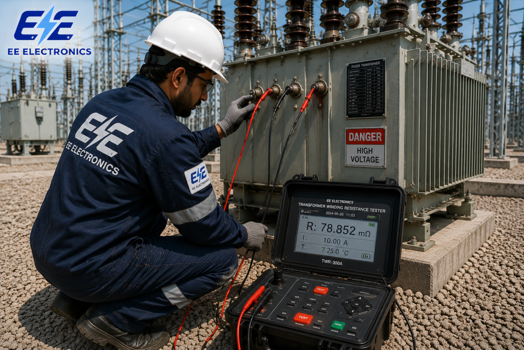
Connections, tap changer contacts and demagnetisation.

Winding deformation after transport or faults.


Timing and contact resistance of the breakers.
Browse by category
 MV/HV Test EquipmentTTR, winding resistance, SFRA, VLF and relay testing
 Electrical & Electronic EquipmentMultimeters, clamp meters, IR and earth testers
 Safety & Protection EquipmentHV detectors, gloves, earthing sets
 Measurement & CalibrationElectrical, process and temperature calibrators
 Solar PV Testing EquipmentPV testers, IV curve tracers
 Training & Engineering SolutionsTesting, calibration and safety training
Frequently asked questions
What is a TTR test?
A TTR (transformer turns ratio) test measures the ratio of turns between the HV and LV windings of a transformer and compares it with the ratio calculated from the nameplate and vector group. It detects shorted or open turns, tap changer faults and wrong connections.
What is the acceptable limit for a TTR test?
The usual limit is ±0.5% of the calculated ratio (IEEE C57.12.00 and C57.152; NETA uses the same figure). Under IEC 60076-1, the principal tap must be within the lower of ±0.5% or one tenth of the percentage impedance.
How is the TTR test done on a three-phase transformer?
The transformer is isolated and earthed, and the TTR tester is connected to the HV and LV bushings. The vector group is entered so the tester can calculate the expected ratio, and the ratio, phase deviation and excitation current are measured on every phase and every tap.
What voltage is used for a TTR test?
TTR testers use low AC voltages. Hand-held testers typically apply 8 V (1.5 V for CTs), benchtop testers offer voltages such as 40 V and 80 V, and three-phase testers can apply up to around 250 V. Higher voltages improve accuracy on high-ratio transformers.
Why is the TTR test done on all taps?
Each tap changes the number of turns, so each tap has its own expected ratio. Testing every tap finds faults in the tap changer, its contacts and its leads that would not show on the principal tap.
What is the difference between a TTR test and a winding resistance test?
The TTR test checks the number of turns and the connections using a low AC voltage. The winding resistance test uses DC current to check the resistance of the windings, connections and tap changer contacts. They complement each other, and the TTR test is usually run first.
Can a TTR test detect shorted turns?
Usually, yes. Shorted turns change the ratio and increase the excitation current. A small number of shorted turns can leave the ratio within limits, which is why excitation current and phase deviation should always be recorded too.
Where can I buy a TTR tester in Jordan?
EE Electronics supplies hand-held, single-phase and three-phase TTR testers and the rest of the transformer test equipment range from its office in Khalda, Amman. Send your transformer ratings for a quotation within 24 hours.
Testing transformers in Jordan? Get the right TTR tester.
Tell EE Electronics about your transformers and tap changers. We will recommend a TTR tester and the instruments that go with it, and reply with a quotation within 24 hours.